2.5. ERD Relationship Types
Relationship Types means: the type of association among entities.
A relationship type can have attributes; for example, HoursPerWeek of WORKS_ON relationship; its value for each relationship instance describes the number of hours per week that an EMPLOYEE works on a PROJECT. HoursPerWeek attribute is neither describing the employee nor the project, but it describes the relation between them (WORKS_ON).
Relationships in the E-R diagram play a vital role as they help in converting any E-R diagram into database related tables.
2.5.1. Relationship Constraints
Constraints are used for modeling limitations on the relations between entities.
There are two types of constraints on the ER-Model (Cardinality ratio & Participation).


2.5.1.2. Relationship Participation
The below visualizations show how to express cardinality and participation constraints using Chen, Crow’s Foot & Min-Max notation in the ER-Model.
2.5.2. Relationship Degree
The degree of a relationship is the number of entity types that participate(associate) in a relationship. (i.e. the number of an entity type that is connected to a relationship is the degree of that relationship)
we have the following degrees of relationships:
Unary
Binary
Ternary
N-ary
Note 1: As all relationship concepts (degree, cardinality & participation) are clear now, it’s time to know how to map an ERD relationship of any degree in to a relational schema diagram. To achieve this all the susbsequant sections discuss individually each degree with all its cardinality constraint options.
Note 2: You should know that the following examples not only show the rigth straight forward cases but they start with illustrating wrong mapping techniques to know its defects. And then the right mapping process is given to the reader to clearly understand the mapping rules.
2.5.2.1. Unary (Recursive) Relationship (degree 1)
In recursive (unary ) relationship both participants are same entity type in different roles.
For example, SUPERVISION relationships between EMPLOYEE (in role of supervisor or boss) and (another) EMPLOYEE (in role of subordinate or worker).
In ER diagram, role names should be displayed to distinguish entities’ participations.
One-To-One Unary Relationship:
One-To-Many Unary Relationship:
Many-To-Many Unary Relationship:
Unary relationship examples conclusions: (Mapping Rules)
1- Unary 1:1, FK is added to the original entity, FK can reference any one of the two roles.
2- Unary 1:M, FK is added to the original entity, BUT FK should references the role of the (1) side.
3- Unary N:M, additional table is added consisting of two FKs each of which references of the roles. Two FKs together act as a composite PK for the new bridge table.
4- Finally any attribute can be added to relationship, in this case the attributes inserted wherever the FK exists.
2.5.2.2. Binary Relationship (degree 2)
A binary relationship exists when exactly two entity type participates. When such a relationship is present we say that the degree is 2.
This is the most common degree of relationship.
It is easy to deal with such relationship as these can be easily converted into relational tables.
For example, Having two entity types ‘Doctor’ and ‘Patient’ where Doctors connected to Patients through Treats relationship.
One-To-One Binary Relationship:
One-To-Many Binary Relationship:
Many-To-Many Binary Relationship:
Additional Binary relationship example for concept illustration:
You should know that the cardinality of relationship is dependant on the problem specification (application domain requirements). No standered cardinality for for a given relationship type according to specific entities.
The following visualization example shows five different cardinality cases for the same binary relationship type between same entities. (cardinallity differes according to problem statment)
Binary relationship examples conclusions: (Mapping Rules)
1- Binary1:1, PK of any entity can be inserted as a FK in the other entity.
2- Binary1:M, PK of the entity in the (1) side inserted as a FK in entity table beside (M) side.
3- BinaryN:M, additional bridge table is added consisting of the two FKs of the two entities. Two FKs together act as a composite PK for the new bridge table.
4- Finally any attribute can be added to relationship, in this case the attributes inserted wherever the FK exists.
2.5.2.3. Ternary Relationship (degree 3)
A ternary relationship exists when exactly three entity type participates. When such a relationship is present we say that the degree is 3.
As the number of entity increases in the relationship, it becomes complex to convert them into relational tables.
For example, Having three entity type ‘Employee’, ‘Project’ and ‘Equipment’. The relationship between these entities are defined as an employee works in a specific project, using a certain equipment.
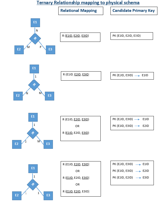
**Ternary relationship examples conclusions: **
1- Any ternary relationship ,regardless of its cardinality, requires a bridge collecting the FKs of the three related entities.
2- See the below image to know PK mapping rules in all cardinality cases.
3- The most widely used cardinality case in real life examples in the ternary relationship is the N:M:P.
4- In general, a ternary relationship is not equivalent to 3 binary relationships. (V.V.I)
5- Any relational attribute should be added to the bridge.