2.2. The Unified Modeling Language
2.2.1. The Unified Modeling Language
The Unified Modeling Language, or UML, is an industry standard graphical notation for describing and analysing software designs. The symbols and graphs used in the UML are an outgrowth of efforts in the 1980’s and early 1990’s to devise standards for Computer-Aided Software Engineering (CASE). UML represents a unification of these efforts. In 1994 - 1995 several leaders in the development of modeling languages, Grady Booch, Ivar Jacobson, and James Rumbaugh, attempted to unify their work. To eliminate the method fragmentation that they concluded was impeding commercial adoption of modeling tools, they developed UML, which provided a level playing field for all tool vendors.
UML has been accepted as a standard by the Object Management Group [1] (OMG). The OMG is a non-profit organization with about 700 members that sets standards for distributed object-oriented computing.
UML was initially largely funded by the employer of Booch, Jacobson & Rumbaugh, aka the three amigos, Rational Software, which was sold to IBM in 2002.
A software model is any textual or graphic representation of an aspect of a software system. This could include requirements, behavior, states or how the system is installed. The model is not the actual system, rather it describes different aspects of the system to be developed. UML defines a set of diagrams and corresponding rules that can be used to model a system. The diagrams in the UML are generally divided into two broad categories or views, static and dynamic.
This course does not provide anywhere near a comprehensive review of the UML. The intent is to introduce you to the basics you need to understand the designs presented in this course. Since there is an excellent chance you will encounter the UML or something very similar to it in your professional career and the diagrams used in this course are used not only in the UML, but in other modeling systems as well [2] [3] [4].
2.2.1.1. Static and Dynamic Diagrams
Static diagrams emphasize the static structure of the system, its objects’ attributes, methods, and relationships. Static views include:
Class diagrams and
Deployment diagrams
In this course we are primarily interested in class diagrams.
Dynamic diagrams emphasize the dynamic behavior of a system, its states or modes and the collaborations between objects. Dynamic views include:
Sequence diagrams
State diagrams
Use Case diagrams
2.2.1.2. Class Diagrams

The class diagram is one of the most commonly encountered diagrams. It describes the types of objects in a system and the kinds of static relationships that exist among them.
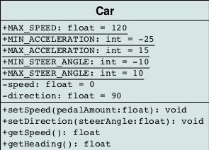
In UML, a class is represented by a rectangle with one or more horizontal compartments. By convention, the class name starts with a capital letter. Another convention is to italicize the class name if the class is an AbstractClass. The top compartment holds the name of the class. The name of the class is the only required field in a class diagram. The middle compartment of the class rectangle holds the list of the class attributes. The bottom compartment holds the list of methods.

Attribute and method visibility is indicated using a single character before the class member. Static members are indicated by underlining the member name. The UML term for static members is classifier members.
The UML syntax for an attribute is: visibility name : type = defaultValue
Symbol |
Visibility |
|---|---|
|
Public |
|
Private |
|
Protected |
|
Derived |
|
Package |
Class diagrams use different notational standards to display class inheritance, class composition, and other associations.
Inheritance relationships

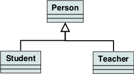
Generalization in action:
Students and Teachers are both People
In the UML, the Inheritance relationship is referred to as a generalization.
Inheritance is drawn as an empty arrow, pointing from the subclass to the superclass. The super class is considered a generalization of the subclass, so it makes sense that the arrow should point to the super class. The arrow is trying to say that the subclass IS A type of the super class.
In the example diagram, two classes inherit from the more general super class. It is not expressly required to draw a single merged set of lines to the super class. Some UML drawing tools draw each inheritance line as a separate straight line to the parent class. This has no impact on the meaning of the relationship. A merged line showing relationships does not imply that the two subclasses are in any way interdependent, other than they share a common ancestor.
Realization relationships
A realization is a relationship between two model elements, in which one model element (the client) realizes (implements or executes) the behavior that the other model element (the supplier) specifies.

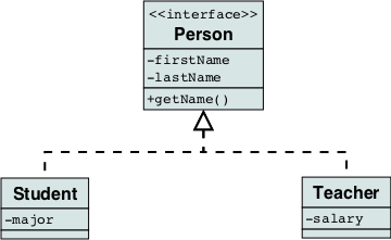
Two classes realizing an interface
The UML graphical representation of a realization is a hollow triangle shape on the interface end of the dashed line (or tree of lines) that connects it to one or more implementers. A plain arrow head is used on the interface end of the dashed line that connects it to its users.
A realization is a relationship between classes, interfaces, components, and packages that connects a client element with a supplier element. A realization relationship between classes and interfaces and between components and interfaces shows that the class realizes the operations offered by the interface.
In this course, we are primarily concerned with relationships between
classes.
Note the addition at the top of the Person class: <<interface>>.
The angle brackets define a stereotype.
The stereotype allows UML modelers to extend the vocabulary of a model
element or to be more specific about the role or purpose of a model
element.
In this case, the stereotype <<interface>> tells us this is not
just any old class, but this class defines an interface.
Notice the similarity between the Generalization relationship and the Realization relationship. Generalization always models inheritance relationships between classes. Realization always models interface implementation relationships between classes.
Association

An association represents a relationship between two classes. An association between two classes is shown by a line joining the two classes. Association indicates that one class utilizes an attribute or methods of another class. If there is no arrow on the line, the association is taken to be bi-directional, that is, both classes hold information about the other class. A unidirectional association is indicated by an arrow pointing from the object which holds to the object that is held.
Association is the least specific type of association. It is used when the classes each have their own life cycle and are independent of each other. For example, two classes might be related because one or both takes the other as a parameter to a method.
public class Author {

  public void write(Book b) {
    // do something with the Book
  }
}
Multiplicity
Associations have a multiplicity (sometimes called cardinality) that
indicates how many objects of each class can legitimately be involved in a given relationship.
Multiplicity is expressed using an n..m notation near one end of the association line,
close to the class whose multiplicity in the association we want to show.
Here n refers to the minimum number of class instances that may be involved
in the association, and m to the maximum number of such instances.
If n = m only the n value is shown.
An optional relationship is expressed by writing 0 as the minimum number.
The wildcard character * is used to represent the concept zero or more.
Example multiplicity values
Cardinality and modality
Multiplicity Values
One-to-one and mandatory
1One-to-one and optional
0..1One-to-many and mandatory
1..*One-to-many and optional
*With lower bound
land upper boundu
l..uWith lower bound
land no upper bound
l..*
Aggregation
If an association conveys information that one object is part of another object, but their lifetimes are independent (they could exist independently), then this relationship is called aggregation.

Aggregation is a form of the HAS A relationship
For example, a university owns various departments (e.g., chemistry), and each department has a number of professors. If the university closes, the departments will no longer exist, but the professors in those departments will continue to exist. Therefore, a University can be seen as a composition of departments, whereas departments have an aggregation of professors. In addition, a Professor could work in more than one department, but a department could not be part of more than one university. For example:
public class Department {

  private Professor prof;

  public void setProf(Professor prof) {
    this.prof = prof;
  }
}
Tip
Use aggregation judiciously
Few things in the UML cause more consternation than aggregation and composition, in particular how they vary from regular association.
The full story is muddled by history. In the pre-UML methods there was a common notation of defining some form of part—whole relationships. The trouble was that each method defined different semantics for these relationships (although to be fair, some of these were pretty semantics free).
So when the time came to standardize, lots of people wanted part—whole relationships, but they couldn’t agree on what they meant. So the UML introduced two relationships.
aggregation (white diamond) has no semantics beyond a regular association. It is, as Jim Rumbaugh puts it, a modeling placebo. People can, and do, use it—but there are no standard meanings for it. I would advise not using it yourself without some form of explanation.
composition (black diamond) does carry semantics. The most particular is that an object can only be part of one composition relationship. So even if both windows and panels can hold menu bars, any instance of menu bar must be held by only one whole. This is a constraint you can’t easily express with the regular multiplicity markers.
—Martin Fowler, AggregationAndComposition blog post 17 May 2003.
Compositon

A car not only has an engine, it owns it.
Composition is even more specific than aggregation. Like aggregation, one class has an instance of another class, but the child class’s instance life cycle is dependent on the parent class’s instance life cycle. In other words, when the parent dies, the child dies.
An example might be two classes Car and Engine. When a Car is created, it comes with an Engine. The Engine can exist only as long as the Car exists. Furthermore, the Engine exists solely for the benefit of the Car that contains the Engine—no other car can use this engine. When the Car is destroyed, the Engine is destroyed. For example:
public class Car {

  private Engine mopar = new Engine();

}


// an alternative method using constructor initialization
public class Car {

  private Engine mopar;

  public Car() {
    mopar = new Engine();
  }
}


// another alternative using lazy initialization
public class Car {

  private Engine mopar;

  public void buildEngine() {
    if (null == mopar) {
      mopar = new Engine();
    }
    mopar.doSomething();
  }
}
Dependency relationships

Dependency is represented when a reference to one class is passed in as a method parameter to another class. For example, an instance of class Book is passed in to a method of class Customer:
public class Customer {

  public void purchase(Book b) {}
}
The Customer class requires the Book class to function, but doesn’t own it. The caller of the purchase method is required to supply a Book.
More example diagrams and explanations can be viewed at uml-diagrams.org.


